AMDGPU - Memory Organization and Access
Understanding GPU Memory Organization
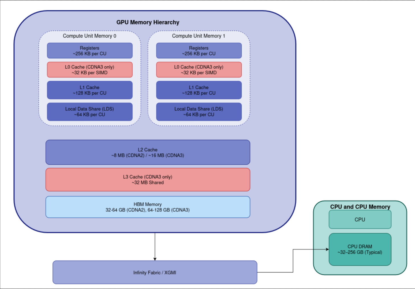
Modern AMD GPUs, particularly the MI250X and MI300X based on the CDNA architecture, implement a deeply hierarchical memory system. Each level is optimized for specific access patterns, ranging from ultra-low-latency register access to high-bandwidth HBM stacks. Here’s a breakdown of the major memory components:
Register File
The fastest level in the memory hierarchy. Registers are directly accessed by scalar and vector units with a latency of just 1–2 cycles. They are private to each wavefront and provide extremely high aggregate bandwidth — typically over 40 TB/s across a compute unit.Local Data Share (LDS)
LDS is a low-latency, explicitly managed memory shared among threads of a single workgroup. It is physically private to each Compute Unit (CU) and scoped per workgroup. This makes it ideal for intra-group communication and scratchpad-style use.L1 Cache
Each CU contains separate L1 caches for scalar and vector operations, each typically 16 KB in size. These caches are private per CU and help minimize accesses to lower levels in the hierarchy.- L2 Cache
The L2 cache is shared across all CUs within a GCD or XCD:- MI250X (CDNA2): 2 MB L2 cache per GCD
- MI300X (CDNA3): 4 MB per XCD
This acts as a mid-level cache to reduce traffic to high-latency HBM memory.
- High Bandwidth Memory (HBM)
The main memory pool accessed by the GPU, providing large capacity and extreme bandwidth:- MI250X (CDNA2): Uses HBM2e, with 4 stacks per GCD, totaling 128 GB and delivering up to 3.2 TB/s bandwidth.
- MI300X (CDNA3): Uses HBM3, with 8 stacks shared across all XCDs, providing 192 GB and up to 5.3 TB/s aggregate bandwidth.
HBM is uniformly accessible from all GCDs/XCDs via ROCm’s unified memory support.
- L3 Infinity Cache (CDNA3 only)
The L3 Infinity Cache, introduced in CDNA3, is available per GPU package and acts as a high-speed buffer for inter-GCD data transfers. It helps reduce remote memory latency and increases effective bandwidth for cross-die access.Note: The L3 Infinity Cache is only present in CDNA3 GPUs like the MI300X and is not shown in the diagram below, which focuses on components common to both CDNA2 and CDNA3.
This layered memory architecture allows AMD GPUs to effectively support both latency-sensitive control flows and throughput-bound data-parallel workloads, making them suitable for scientific computing, AI training, and inference at scale.
Memory Organization of Interconnected GPUs (Within the Same Node)
Starting with the CDNA2 (Compute DNA 2) architecture, AMD adopted a chiplet-based design, where multiple Graphics Compute Dies (GCDs) are integrated into a single GPU package. This architectural shift enables better thermal and power efficiency while improving scalability.
Each GCD in such a package is a fully functional GPU in its own right, equipped with:
- Its own Compute Units (CUs) and Command Processors
- A dedicated L2 Cache
- A direct memory access path to High-Bandwidth Memory (HBM)
For example:
- The MI250X contains two GCDs per package
- The MI300X includes multiple GCDs and may also integrate CPU dies and HBM in a single APU-style design
From a programming perspective, each GCD is exposed as an independent GPU device. Applications can target them individually or coordinate workloads across them using APIs like HIP and ROCm.
The memory hierarchy in such interconnected GPU systems is extended and coordinated across dies. A critical component that enables this is the Infinity Fabric Switch, which:
- Connects multiple GCDs within the package
- Enables high-bandwidth, low-latency communication
- Supports cache-coherent or non-coherent memory sharing, depending on the configuration
This design allows multi-GPU packages to scale compute performance while maintaining efficient memory access across chiplets, a crucial feature for AI, HPC, and data-intensive workloads.
1
2
3
4
5
6
7
8
9
10
11
12
13
14
15
16
17
18
19
20
21
22
23
24
25
26
27
28
29
30
31
                       ≈≈≈≈≈≈≈≈≈≈≈≈≈≈≈≈≈≈≈≈≈≈≈≈≈≈≈≈≈≈≈
                       ||        XGMI / PCIe Gen5   ||
                       ≈≈≈≈≈≈≈≈≈≈≈≈≈≈≈≈≈≈≈≈≈≈≈≈≈≈≈≈≈≈≈
                                ↑
                        ┌───────┴───────┐
                        │   Interconnect│ (Infinity Fabric Switch)
                        └───────┬───────┘
                                │  ~1 TB/s aggregate IF BW
   ┌────────────────────────────┼────────────────────────────┐
   │                            │                            │
   ▼                            ▼                            ▼
┌────────────┐         ┌────────────┐                ┌────────────┐
│  GCD 0     │         │  GCD 1     │                │  GCD N     │  ← Up to 8 GCDs
│ (NUMA 0)   │         │ (NUMA 1)   │                │ (NUMA N)   │
│ ┌───────┐  │         │ ┌───────┐  │                │ ┌───────┐  │
│ │CU x64 │  │         │ │CU x64 │  │   ...          │ │CU x64 │  │
│ └───────┘  │         │ └───────┘  │                │ └───────┘  │
│   ▲        │         │   ▲        │                │   ▲        │
│   │64 KB   │         │   │64 KB   │                │   │64 KB   │
│   │LDS/SGPR│         │   │LDS/SGPR│                │   │LDS/SGPR│
│   ▼        │         │   ▼        │                │   ▼        │
 HBM3 (1TB/s)           HBM3 (1 TB/s)                 HBM3 (1 TB/s)
└────┬───────┘         └────┬───────┘                └────┬───────┘
     │                      │                             │
     ▼                      ▼                             ▼

       ╔═════════════════════════════════════════════════════╗
       ║            Shared L3 Infinity Cache (~256MB)        ║
       ║        Unified across all GCDs (~5 TB/s IF BW)      ║
       ╚═════════════════════════════════════════════════════╝
Inter-GPU Communication (including across GPU packages)
AMD uses XGMI (External Global Memory Interconnect) for inter-GPU package communication. This link can achieve bandwidths of up to 64 GB/s. On the MI250X, GPUs are connected in a mesh topology, while on the MI300X, GPUs use a ring topology for interconnection.
Programming Model
Accessing memory on a peer GPU is supported in HIP through the following methods:
- Direct Access: A GPU can directly access memory allocated on a peer GPU, once the memory is mapped and access is enabled.
- Explicit Copy: Use HIP APIs (e.g.,
hipMemcpyPeer) to explicitly copy memory between GPUs.
To enable either method, you must call hipDeviceEnablePeerAccess. The example below shows how to enable peer access and use memory allocated on GPU 0 from GPU 1:
1
2
3
4
5
6
7
8
9
10
11
12
13
14
15
16
17
18
19
20
21
22
23
24
25
26
27
28
29
30
31
32
33
34
35
36
37
38
39
40
41
42
43
44
45
46
47
48
49
50
51
52
53
54
55
56
57
58
59
60
61
#include <hip/hip_runtime.h>
#include <cstdio>

// Simple kernel to write to device memory
__global__ void writeKernel(int* data, int value) {
    int idx = threadIdx.x + blockIdx.x * blockDim.x;
    if (idx == 0) data[0] = value;
}

int main() {
    int deviceCount = 0;
    hipGetDeviceCount(&deviceCount);
    if (deviceCount < 2) {
        printf("Need at least 2 devices for peer access example.\n");
        return 1;
    }

    // Set devices
    int dev0 = 0;
    int dev1 = 1;

	int can_access;
	hipSetDevice(dev0);
	hipDeviceCanAccessPeer(&can_access, dev0, dev1);
	if (can_access) {
	    // Enable peer access from dev0 to dev1 and vice versa
	    hipDeviceEnablePeerAccess(dev1, 0);
	}

	hipSetDevice(dev1);
	hipDeviceCanAccessPeer(&can_access, dev1, dev0);
	if (can_access) {
	    // Enable peer access from dev0 to dev1 and vice versa
	    hipDeviceEnablePeerAccess(dev0, 0);
    }

    // Allocate memory on dev0
    hipSetDevice(dev0);
    int* d_data = nullptr;
    hipMalloc(&d_data, sizeof(int));

    // Launch kernel on dev1 that writes to dev0's memory
    hipSetDevice(dev1);

    // Launch kernel on dev1 with d_data pointer allocated on dev0
    writeKernel<<<1, 1>>>(d_data, 123);

    hipDeviceSynchronize();

    // Copy result back to host
    int host_data = 0;
    hipMemcpy(&host_data, d_data, sizeof(int), hipMemcpyDeviceToHost);

    printf("Value written from device 1 kernel to device 0 memory: %d\n", host_data);

    // Cleanup
    hipSetDevice(dev0);
    hipFree(d_data);

    return 0;
}
Using hipMemcpyPeer for Inter-GPU Communication
Another way to enable inter-GPU communication is by using the hipMemcpyPeer API, which allows direct memory copying between GPUs. An example is provided below.
💡 As with most HIP memory operations, an asynchronous version of this API,
hipMemcpyPeerAsync, is also available to perform the transfer without blocking the host.
1
2
3
4
5
6
7
8
9
10
11
12
13
14
15
16
17
18
19
20
21
22
23
24
25
26
27
28
29
30
31
32
33
34
35
36
37
38
39
40
41
42
43
44
45
46
47
48
49
50
51
#include <hip/hip_runtime.h>
#include <cstdio>

int main() {
    int deviceCount = 0;
    hipGetDeviceCount(&deviceCount);
    if (deviceCount < 2) {
        printf("Need at least 2 devices for peer copy example.\n");
        return 1;
    }

    int dev0 = 0;
    int dev1 = 1;

    // Enable peer access between devices
    hipSetDevice(dev0);
    hipDeviceEnablePeerAccess(dev1, 0);

    hipSetDevice(dev1);
    hipDeviceEnablePeerAccess(dev0, 0);

    // Allocate memory on both devices
    hipSetDevice(dev0);
    int* d_src = nullptr;
    hipMalloc(&d_src, sizeof(int));
    int h_value = 42;
    hipMemcpy(d_src, &h_value, sizeof(int), hipMemcpyHostToDevice);

    hipSetDevice(dev1);
    int* d_dst = nullptr;
    hipMalloc(&d_dst, sizeof(int));

    // Perform peer-to-peer copy: dev0's memory -> dev1's memory
    hipMemcpyPeer(d_dst, dev1, d_src, dev0, sizeof(int));
    // hipMemcpyPeerAsync(dst, dstDevice, src, srcDevice, size, stream);

    // Copy back to host to verify
    int h_result = 0;
    hipMemcpy(&h_result, d_dst, sizeof(int), hipMemcpyDeviceToHost);

    printf("Value copied from device %d to device %d: %d\n", dev0, dev1, h_result);

    // Cleanup
    hipSetDevice(dev0);
    hipFree(d_src);

    hipSetDevice(dev1);
    hipFree(d_dst);

    return 0;
}
Inter-GPU Access Across Packages via XGMI and ROCm UVM
Inter-GPU memory access works seamlessly even when GPUs are on different packages. In such scenarios, memory access is routed through the XGMI bus. AMD’s ROCm stack supports this through UVM (Unified Virtual Memory), which provides a global virtual address space shared across:
- Multiple GPUs (even on different packages),
- The CPU, and
- All GPU Compute Dies (GCDs or XCDs).
This seamless addressability is made possible through collaboration between ROCm runtime, kernel driver (KFD), and hardware support.
🧠 How the Address Space is Structured
- Each GCD (XCD) on each package receives its own 64-bit virtual address segment.
- These segments are disjoint and non-overlapping.
- All allocations (e.g., via
hipMalloc,hipMallocManaged, or low-level APIs) are assigned addresses from these segments. - The CPU can see and map this global virtual address space — mapping either to system DRAM (host) or GPU HBM (device), depending on the memory’s location and HMM migration status.
Below is a hypothetical address layout showing how different GCDs are assigned distinct address ranges at runtime:
| Package | GCD (XCD) | Virtual Address Range (Example) | Notes |
|---|---|---|---|
| 1 | 0 | 0x0000_0000_0000_0000–0x0000_0057_FFFF_FFFF | 24 GB segment |
| 1 | 1 | 0x0000_0058_0000_0000–0x0000_00AF_FFFF_FFFF | Next 24 GB segment |
| 2 | 0 | 0x0000_00B0_0000_0000–0x0000_0107_FFFF_FFFF | Separate 24 GB segment |
| 2 | 1 | 0x0000_0108_0000_0000–0x0000_015F_FFFF_FFFF | Another unique 24 GB range |
📝 Note:
- These addresses are not fixed or hard-coded.
- The ROCm driver dynamically allocates virtual address space at runtime.
- A global VA pool is maintained per process.
- Each allocation gets a unique VA range, ensuring no conflicts between different GPUs or packages.
This design allows any GPU or CPU core to dereference pointers from this unified space without requiring explicit address translation by the programmer.
AMD GPUs and Heterogeneous Memory Management (HMM)
HMM enables GPU-like devices to share a virtual address space seamlessly with the CPU. It has been part of the Linux kernel since version 4.8 and has evolved to handle important responsibilities such as:
- Allowing devices to mirror CPU page tables,
- Enabling devices to page-fault just like CPUs,
- Maintaining ownership, coherence, and synchronization of shared memory pages.
Let’s discuss various scenarios that can originate between the GPU and CPU regarding memory handling.
Accessing GPU Memory from a CPU Program
Consider the following example:
1
2
3
4
5
6
7
8
int *gpu_data;
hipMalloc(&gpu_data, sizeof(int) * 10);

kernel_write<<<1, 10>>>(gpu_data);
hipDeviceSynchronize();

for (int i = 0; i < 10; ++i)
    std::cout << gpu_data[i] << std::endl;
What Happens Internally
- Step 1: Allocate memory using
hipMallochipMallocallocates memory on a specific GPU.- ROCm runtime requests memory allocation via HSAKMT (ROCr’s kernel-mode thunk).
- GCD-specific physical memory is allocated in HBM (High Bandwidth Memory).
- A virtual address is assigned from ROCm’s Unified Virtual Address (UVA) space.
- Step 2: Kernel Execution
- The kernel writes data to the allocated GPU memory.
- Step 3: CPU Access
- When the CPU dereferences
gpu_data[i], a page fault occurs because:- The GPU memory page is not yet present in the CPU’s page tables.
- Linux HMM handles this by:
- Triggering a
page_fault()in the ROCm kernel driver (amdgpu_vm_fault()). - Migrating the page from GPU memory to CPU memory (if migration is permitted), or
- Allowing the CPU to read the pinned GPU page directly over PCIe/XGMI.
- Triggering a
- When the CPU dereferences
- Step 4: Data Coherence
- An explicit
hipDeviceSynchronize()call is required to ensure kernel completion. - CPU-side access becomes coherent only after synchronization.
- An explicit
Accessing CPU Memory from GPU Kernel
Consider the example below
1
2
3
4
5
6
7
8
int *host_data;
hipHostMalloc(&host_data, sizeof(int) * 10, hipHostMallocMapped);

int *dev_ptr;
hipHostGetDevicePointer(&dev_ptr, host_data, 0);

kernel_use_host_data<<<1, 10>>>(dev_ptr);
hipDeviceSynchronize();
What Happens Internally
- Step 1: Allocation
hipHostMallocMappedallocates pinned system memory.- The memory is mapped into both CPU and GPU address spaces.
- UVA ensures the same virtual address range is visible across devices.
- Step 2: GPU Access
- The kernel dereferences
dev_ptr[i]. - If the page is not resident on the GPU, it triggers a GPU-side page fault.
- The kernel dereferences
- HMM + IOMMU + ROCr
- Maps CPU physical pages into the GPU’s page table.
- Transfers pages over PCIe/XGMI if needed.
- If the GPU supports HMM prefetching, it may migrate multiple pages at once.
- Memory Coherence
- The ROCm runtime guarantees sequential coherence between CPU and GPU if proper synchronization is performed (e.g., via
hipDeviceSynchronize()).
- The ROCm runtime guarantees sequential coherence between CPU and GPU if proper synchronization is performed (e.g., via
Accessing GPU Memory from Another GPU (Peer Access)
Consider the example
1
2
3
4
5
6
7
8
9
10
hipSetDevice(0);
int *gpu0_ptr;
hipMalloc(&gpu0_ptr, sizeof(int) * 10);
fill_kernel<<<1, 10>>>(gpu0_ptr);
hipDeviceSynchronize();

hipSetDevice(1);
hipDeviceEnablePeerAccess(1, 0);
peer_read_kernel<<<1, 10>>>(gpu0_ptr);
hipDeviceSynchronize();
What Happens Internally
- Step 1: Allocation
- Memory is allocated from GPU 0’s memory pool.
- A virtual address (VA) is assigned from ROCm’s Unified Virtual Address (UVA) space, which is valid globally across GPUs.
- Step 2: Peer Access Setup
- Calling
hipDeviceEnablePeerAccess(0)instructs ROCr to set up cross-GPU page table mappings. - GPU 1 receives MMU mappings to access GPU 0’s memory directly.
- If the GPUs are on different packages, this communication happens over XGMI links (e.g., between GCDs on MI250X or across packages).
- Calling
- Step 3: Remote GPU Access
- GPU 1 accesses the remote memory page.
- Depending on the hardware and configuration:
- Direct access is performed via XGMI or Infinity Fabric links to GPU 0’s HBM.
- Or page migration occurs through ROCr and the ROCm SVM subsystem if migration is permitted.
- Step 4: Synchronization
- Proper synchronization (e.g.,
hipDeviceSynchronize()) is required to prevent data races and ensure data consistency across GPUs.
- Proper synchronization (e.g.,
Two AMD GPUs access the same hipMallocManaged memory
Consider a program like this
1
2
3
4
5
6
7
8
9
10
11
12
13
14
15
16
17
18
19
20
21
22
23
24
25
26
27
28
29
30
#include <hip/hip_runtime.h>
#include <iostream>

__global__ void write_kernel(int *data, int offset, int val) {
    int idx = blockIdx.x * blockDim.x + threadIdx.x;
    data[idx + offset] = val;
}

int main() {
    const int N = 1024;
    int *data;

    hipMallocManaged(&data, N * sizeof(int));

    // GPU 0 writes to first half
    hipSetDevice(0);
    write_kernel<<<1, 512>>>(data, 0, 100);

    // GPU 1 writes to second half
    hipSetDevice(1);
    write_kernel<<<1, 512>>>(data, 512, 200);

    hipDeviceSynchronize();

    std::cout << data[0] << " " << data[511] << " "
              << data[512] << " " << data[1023] << std::endl;

    hipFree(data);
    return 0;
}
What Happens Internally
- Step 1: Unified Memory Allocation
hipMallocManagedallocates memory in CPU DRAM.- The memory is registered with ROCm and the Linux kernel via Heterogeneous Memory Management (HMM).
- A Unified Virtual Address (UVA) is returned — valid on all GPUs and the CPU.
- ROCm instructs the kernel to mark the range as HMM-managed.
- Initially, no GPU has a valid mapping to this memory.
- The pages reside in CPU DRAM and are owned by the CPU.
- Step 2: GPU 0 Launches Kernel
- GPU 0 accesses
data[0..511]. - Since GPU 0 has no mapping for these pages, it triggers GPU page faults.
- ROCm’s kernel driver (AMDKFD) handles the fault by invoking
hmm_range_fault(), which walks the CPU page tables. - CPU pages
data[0..511]are pinned. - Their physical addresses are returned.
- Mappings are installed in GPU 0’s MMU.
- GPU 0 can now access these CPU pages directly over PCIe/XGMI and writes data.
- GPU 0 accesses
- Step 3: GPU 1 Launches Kernel
- GPU 1 accesses
data[512..1023], which is not yet mapped. - The same page fault handling occurs, updating GPU 1’s MMU mappings accordingly.
- GPU 1 accesses
- Step 4:
hipDeviceSynchronize()- Synchronizes to wait for both GPUs to finish execution.
- Ensures all DMA writes to CPU DRAM are completed.
- Enforces proper memory ordering.
Note: Explicit synchronization is required if GPU accesses overlap to avoid data races or incoherent memory states.
Atomic Operations on Shared Memory
When a GPU performs atomic operations (such as atomic adds or compare-and-swap (CAS)) on shared memory (CPU or peer GPU memory):
- HMM does not guarantee atomicity across CPU and GPU.
- Only intra-GPU atomic operations are guaranteed to be fast and coherent.